




Products Description
A wastewater sewage grinder reduces the size of coarse solids carried in sewage before they reach downstream pumps, pipes and treatment equipment. It is commonly considered for sewage pumping stations, wastewater collection systems and other installations where rags, fibrous materials and miscellaneous solid waste may cause blockages.
Unlike a conventional bar screen, which retains and removes screenings, a grinder cuts or shreds suitable solids into smaller pieces. The shredded material generally continues downstream with the wastewater. This means a grinder can reduce the need to handle screenings at the installation, but it does not remove the solid material from the wastewater.
The right arrangement depends on the incoming flow, the type and quantity of solids, the channel or pipeline layout, and the requirements of the downstream equipment.
Where Is a Wastewater Sewage Grinder Used?
Sewage pumping stations
A grinder can be installed upstream of pumps where fibrous or bulky solids create a recurring risk of blockage. The grinder must be selected to suit the station's flow conditions and the solids expected in the sewage.
Municipal wastewater collection systems
In collection networks and lift stations, a channel grinder can reduce the size of suitable coarse solids before the wastewater moves to the next stage of the system.
Industrial wastewater pretreatment
Certain industrial wastewater streams contain rags, packaging fragments or other coarse solids that may interfere with pumps and downstream equipment. The wastewater composition should be checked before selecting a grinder, especially if the stream contains abrasive, corrosive or unusually hard materials.
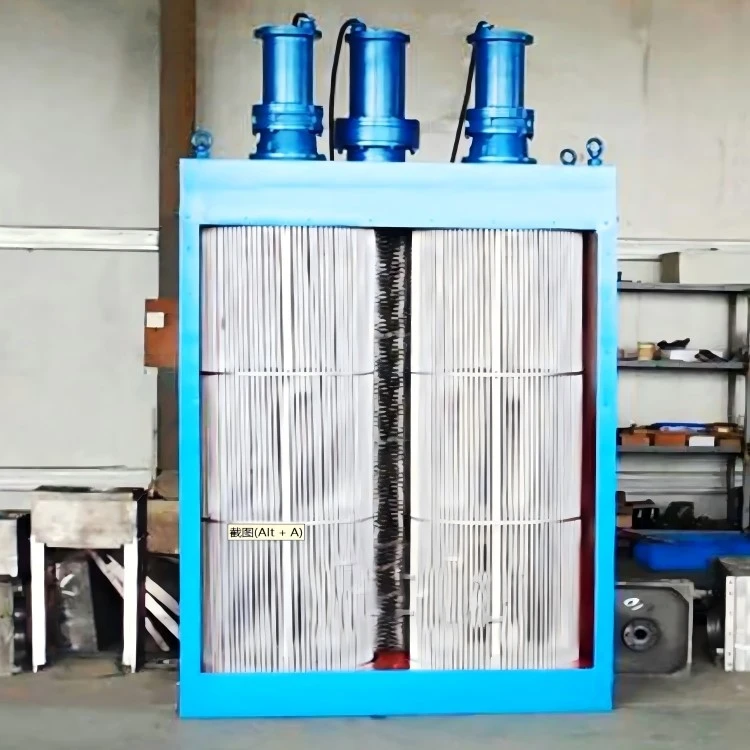
Feature
Small land occupation and reduced civil engineering costs: The wastewater sewage grinder requires a smaller width and depth for the water inlet channel under the same flow rate, compared to traditional screens. This not only reduces the land area needed but also minimizes the amount of earth excavation, thereby saving on civil engineering costs.
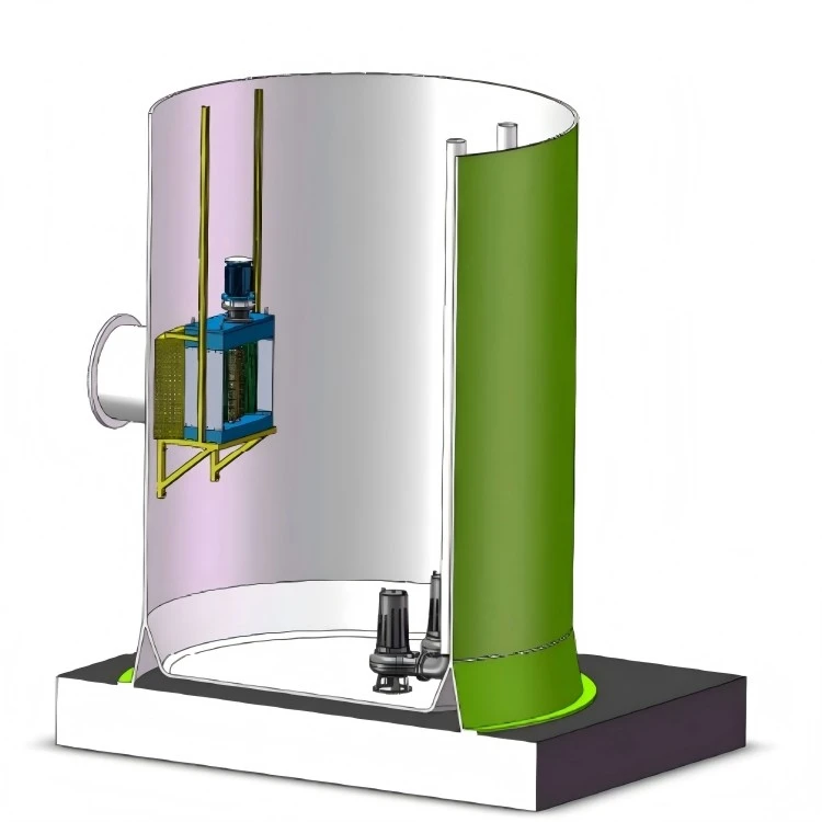
Fully automated, fully buried intelligent operation: Pump stations using traditional screens have a low degree of automation and require manual management. They also need to be equipped with management rooms, resulting in significant investment. In contrast, pump stations using crushing screens come with their own PLC system, offering user-friendly expansion functions for intelligent and remote management. This enables unified management and joint control of multiple pump stations.
Reduce personnel expenses and operating costs: Traditional screen residues still require manual cleaning at regular intervals. The crushing screen, on the other hand, implements centralized control and an unmanned system, significantly reducing operating costs associated with pump station management.
Protect the environment and reduce pollution: Traditional screens require the salvaging of screen residue, which means the pump station remains open. This exposes harmful odors and toxic substances to the air, negatively impacting the surrounding environment. With the crushing screen, the entire pump station can be buried underground, and greenery can be planted on top. This reduces odor leakage, minimizes operating noise, and improves the environmental quality around the pump station.
Higher initial investment, but better long-term value: While the one-time investment cost of the crushing screen is slightly higher than that of traditional screens, a comprehensive evaluation-considering the pump station's construction scale, personnel costs, long-term effects, and environmental benefits-shows that the crushing screen far outperforms traditional mechanical screens.

How Does a Wastewater Sewage Grinder Work?
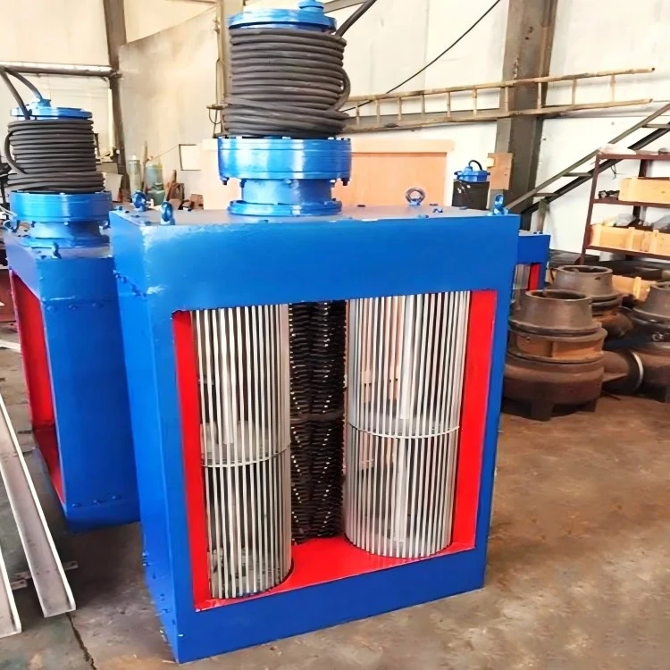
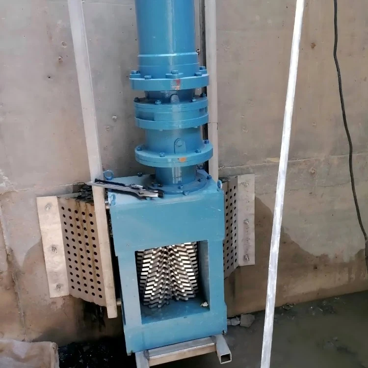
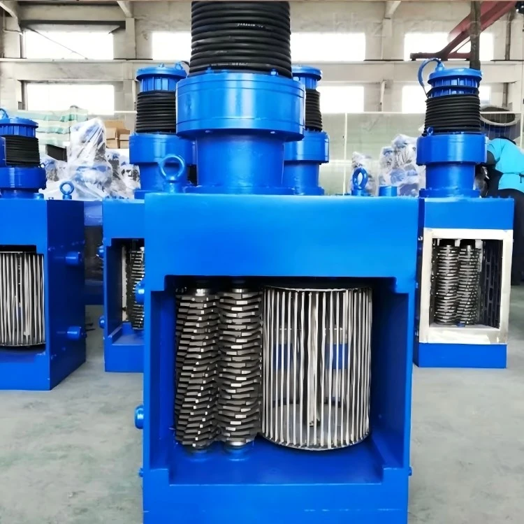
In a typical twin-shaft channel grinder, wastewater passes through a cutting assembly containing two rotating shafts fitted with intermeshing cutters and spacers. As the shafts rotate, the cutters draw in and shear suitable solids into smaller pieces.
Depending on the design, a grinder may include a motor, gearbox, cutting assembly, frame or housing, and a control system. Some configurations include a drum or screening section, while others use a different inlet arrangement. The actual construction depends on the model selected.
The equipment reduces the size of captured or entrained solids; it is not a substitute for every type of screening or pretreatment. The suitability of the resulting particle size must be considered alongside the clearances and blockage risks of downstream pumps, valves and pipes.
Installation
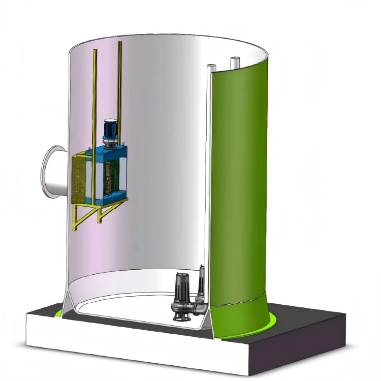

Specification of wastewater sewage grinder without drum

|
model |
A |
B |
C |
|
WFS100 |
250 |
380 |
140 |
|
WFS200 |
250 |
380 |
140 |
|
WFS300 |
250 |
380 |
140 |
|
WFS400 |
250 |
380 |
140 |
|
WFS500 |
250 |
380 |
140 |
|
WFS600 |
250 |
380 |
140 |
|
WFS700 |
250 |
380 |
140 |
|
WFS800 |
250 |
380 |
140 |
|
WFS900 |
250 |
380 |
140 |
|
model |
D |
E |
F |
|
WFS100 |
80 |
440 |
900 |
|
WFS200 |
180 |
540 |
1000 |
|
WFS300 |
280 |
640 |
1100 |
|
WFS400 |
380 |
740 |
1200 |
|
WFS500 |
480 |
840 |
1300 |
|
WFS600 |
580 |
940 |
1400 |
|
WFS700 |
680 |
1040 |
1500 |
|
WFS800 |
780 |
1140 |
1600 |
|
WFS900 |
880 |
1240 |
1700 |
|
model |
flow rate m³/h |
power Kw |
weight Kg |
|
WFS100 |
30 |
2.2 |
190 |
|
WFS200 |
60 |
2.2 |
210 |
|
WFS300 |
90 |
2.2 |
230 |
|
WFS400 |
120 |
2.2 |
250 |
|
WFS500 |
150 |
2.2 |
270 |
|
WFS600 |
180 |
2.2 |
290 |
|
WFS700 |
210 |
2.2 |
310 |
|
WFS800 |
240 |
2.2 |
330 |
|
WFS900 |
270 |
2.2 |
350 |
Specification of wastewater sewage grinder with single drum
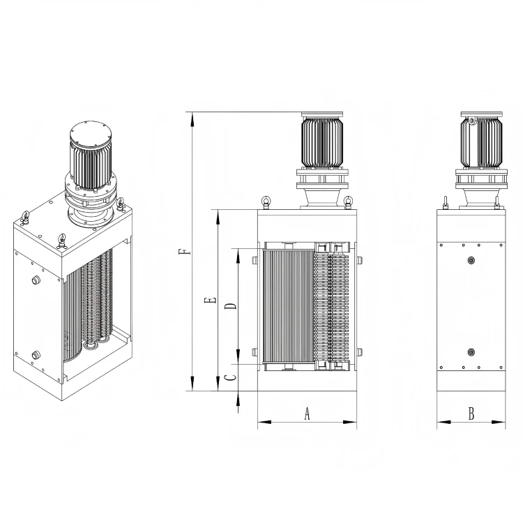
|
model |
A |
B |
C |
|
DFS300×300 |
580 |
400 |
160 |
|
DFS400×300 |
580 |
400 |
160 |
|
DFS500×300 |
580 |
400 |
160 |
|
DFS600×300 |
580 |
400 |
160 |
|
DFS700×300 |
580 |
400 |
160 |
|
DFS800×300 |
580 |
400 |
160 |
|
DFS900×300 |
580 |
400 |
160 |
|
DFS1000×300 |
580 |
400 |
160 |
|
DFS1100×300 |
580 |
400 |
160 |
|
DFS1200×300 |
580 |
400 |
160 |
|
DFS1300×300 |
580 |
400 |
160 |
|
DFS1400×300 |
580 |
400 |
160 |
|
DFS1500×300 |
580 |
400 |
160 |
|
model |
D |
E |
F |
|
DFS300×300 |
280 |
680 |
1220 |
|
DFS400×300 |
280 |
780 |
1320 |
|
DFS500×300 |
280 |
880 |
1420 |
|
DFS600×300 |
280 |
980 |
1520 |
|
DFS700×300 |
280 |
1080 |
1620 |
|
DFS800×300 |
280 |
1180 |
1720 |
|
DFS900×300 |
280 |
1280 |
1820 |
|
DFS1000×300 |
280 |
1380 |
1920 |
|
DFS1100×300 |
280 |
1480 |
2020 |
|
DFS1200×300 |
280 |
1580 |
2120 |
|
DFS1300×300 |
280 |
1680 |
2220 |
|
DFS1400×300 |
280 |
1780 |
2320 |
|
DFS1500×300 |
280 |
1880 |
2420 |
|
model |
flow rate m³/h |
power Kw |
weight Kg |
|
DFS300×300 |
314 |
3 |
372 |
|
DFS400×300 |
432 |
3 |
393 |
|
DFS500×300 |
550 |
3 |
414 |
|
DFS600×300 |
668 |
3 |
435 |
|
DFS700×300 |
786 |
3 |
456 |
|
DFS800×300 |
904 |
3 |
477 |
|
DFS900×300 |
1022 |
3 |
498 |
|
DFS1000×300 |
1140 |
3 |
519 |
|
DFS1100×300 |
1258 |
3 |
540 |
|
DFS1200×300 |
1376 |
3 |
561 |
|
DFS1300×300 |
1494 |
3 |
582 |
|
DFS1400×300 |
1612 |
3 |
603 |
|
DFS1500×300 |
1730 |
3 |
624 |
Specification of wastewater sewage grinder with double drum
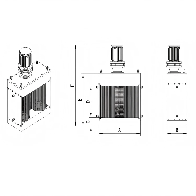
|
model |
A |
B |
C |
|
FS300×300 |
850 |
400 |
160 |
|
FS400×300 |
850 |
400 |
160 |
|
FS500×300 |
850 |
400 |
160 |
|
FS600×300 |
850 |
400 |
160 |
|
FS700×300 |
850 |
400 |
160 |
|
FS800×300 |
850 |
400 |
160 |
|
FS900×300 |
850 |
400 |
160 |
|
FS1000×300 |
850 |
400 |
160 |
|
FS1100×300 |
850 |
400 |
160 |
|
FS1200×300 |
850 |
400 |
160 |
|
FS1300×300 |
850 |
400 |
160 |
|
FS1400×300 |
850 |
400 |
160 |
|
FS1500×300 |
850 |
400 |
160 |
|
FS1600×300 |
850 |
400 |
160 |
|
FS1700×300 |
850 |
400 |
160 |
|
FS1800×300 |
850 |
400 |
160 |
|
FS1900×300 |
850 |
400 |
160 |
|
FS2000×300 |
850 |
400 |
160 |
|
model |
D |
E |
F |
|
FS300×300 |
280 |
680 |
1220 |
|
FS400×300 |
280 |
780 |
1320 |
|
FS500×300 |
280 |
880 |
1420 |
|
FS600×300 |
280 |
980 |
1520 |
|
FS700×300 |
280 |
1080 |
1620 |
|
FS800×300 |
280 |
1180 |
1720 |
|
FS900×300 |
280 |
1280 |
1820 |
|
FS1000×300 |
280 |
1380 |
1920 |
|
FS1100×300 |
280 |
1480 |
2020 |
|
FS1200×300 |
280 |
1580 |
2120 |
|
FS1300×300 |
280 |
1680 |
2220 |
|
FS1400×300 |
280 |
1780 |
2320 |
|
FS1500×300 |
280 |
1880 |
2420 |
|
FS1600×300 |
280 |
1980 |
2520 |
|
FS1700×300 |
280 |
2080 |
2620 |
|
FS1800×300 |
280 |
2180 |
2720 |
|
FS1900×300 |
280 |
2280 |
2820 |
|
FS2000×300 |
280 |
2380 |
2920 |
|
model |
flow rate m³/h |
power Kw |
weight Kg |
|
FS300×300 |
618 |
4 |
513 |
|
FS400×300 |
824 |
4 |
539 |
|
FS500×300 |
1030 |
4 |
565 |
|
FS600×300 |
1236 |
4 |
591 |
|
FS700×300 |
1442 |
4 |
617 |
|
FS800×300 |
1648 |
4 |
643 |
|
FS900×300 |
1854 |
4 |
669 |
|
FS1000×300 |
2060 |
4 |
695 |
|
FS1100×300 |
2266 |
4 |
721 |
|
FS1200×300 |
2472 |
4 |
747 |
|
FS1300×300 |
2678 |
4 |
773 |
|
FS1400×300 |
2884 |
4 |
799 |
|
FS1500×300 |
3090 |
5.5 |
825 |
|
FS1600×300 |
3296 |
5.5 |
851 |
|
FS1700×300 |
3502 |
5.5 |
877 |
|
FS1800×300 |
3708 |
5.5 |
903 |
|
FS1900×300 |
3914 |
5.5 |
929 |
|
FS2000×300 |
4120 |
5.5 |
955 |
Technical Description
(I) Overview
The channel grinder includes: box, cutting blade, gasket, blade shaft, drum, bearing, mechanical seal, side plate, reducer, and motor.
The cutting blade features a double-axis design, allowing it to operate continuously under both dry and wet conditions. The cutting blade and gasket are separate, single-piece components.
The two-stage independent cutting blade and gasket are installed on two parallel shafts, overlapping alternately to achieve spiral cutting. The driven shaft rotates in the opposite direction at two-thirds of the speed of the driving shaft.
(II) Structure
Independent Cutting Blade and Gasket
a. The cutting blade and gasket are made of 3Cr13 alloy steel, with a uniform surface grind and hardened to a minimum of 45-50 HRC.
b. The inner holes of the cutting blade and gasket are hexagonal, with a horizontal gap between the shafts not exceeding 0.3mm, ensuring proper blade drive, reducing wear, and increasing gasket pressure.
c. The cutting part consists of a cutting blade group mounted on two shafts. The overlap between the blade group ranges from 1mm to 6mm, achieving maximum efficiency and minimal friction loss.
d. Under peak instantaneous load, the minimum pressure at the tip of the cutting blade is 8737N/KW.
Shaft
a. The driving and driven shafts of the double-shaft cutting blade group are made from 4140 heat-treated hexagonal steel, with tensile strength not less than 1027kPa.
b. The diameter of each hexagonal shaft is 50mm.
Intermediate Support Shaft (For models with a blade height greater than 800mm)
a. The cutting blade group is equipped with a shaft support.
b. The intermediate shaft support provides additional support to handle larger-than-normal inflows and also protects the sealing device.
c. The intermediate shaft support is made of 304 stainless steel and includes two sleeves. The sleeve acts as a bearing, allowing the shaft to rotate freely.
Vertical Rotary Water Drum
a. The drum is made from stainless steel 304, with a drum diameter of 300mm. The diameter of the bars is 8mm, and the gap between the bars is 10mm. The drum rotates continuously under the drive of the gear inside the box, replacing the grid surface.
Bearings and Mechanical Seals
a. The driving and driven shafts of the blade group each have a sealed tapered roller bearing at both ends, allowing the shaft to withstand both axial and radial pressure.
b. The sealing surface is made of tungsten carbide/tungsten carbide.
c. The O-ring is made of BUNA-N nitrile rubber.
d. The mechanical seal is designed for continuous operation under a load of 620kPa and does not require regular lubrication or cleaning.
Side Plate
The inner surface of the side plate has a fixed overflow baffle, reducing the gap between the side plate and the outer diameter of the drum to a maximum of 5mm.
Base and Casing
a. The crushing-type screen box is cast from ductile iron. It includes a guide device that directs solid particles into the crusher, while also protecting the bearings.
Reducer
a. The fully lubricated cycloid reducer is suitable for high-vibration environments and has a 500% shock absorption capacity, with a reduction ratio of 29:1.
b. The input shaft of the reducer is connected to the motor via a spline, and the output shaft is connected to the crushing grid through another spline.
Motor
a. The motor is an IP68 wet and dry submersible type, capable of operating both in the air and when submerged in water. The crushing grid and drum share a single motor, with a motor cable length of 10m.
b. The motor service factor is 1.15. At full load, the efficiency is not less than 85%, and the power factor is not less than 80%.
(III) Electrical Control
The control panel provides independent control for the wastewater grinder.
The panel offers equipment run/stop signals, manual/automatic operation signals, fault signals, and run/stop control signals.
(IV) Safety Measures
If the crusher becomes blocked, the controller will stop the crusher and reverse it to clear the blockage. Once cleared, the controller will return the crusher to normal operation. If the blockage persists, the crusher will reverse twice (a total of three times) within 30 seconds. If the blockage is still not cleared, the controller will stop the crusher motor and activate the fault indicator.
If the crusher and drum are operating normally and there is a sudden power outage, they will resume normal operation when power is restored.
If the crusher stops operating abnormally (e.g., a sudden power outage), the abnormal status indicator will automatically activate when power is restored.
The controller provides overload protection for the motor through an overload relay mounted directly on the pulverizer starter.
Short-circuit protection is provided by installing an appropriate circuit breaker or fuse.
The controller reset is managed through the local switch control panel.
Hot Tags: wastewater sewage grinder, China wastewater sewage grinder manufacturers, suppliers, factory, wastewater screening performance, wastewater screening alternative, wastewater screening tank, stainless steel wastewater screen, wastewater screening producer, municipal wastewater screen


